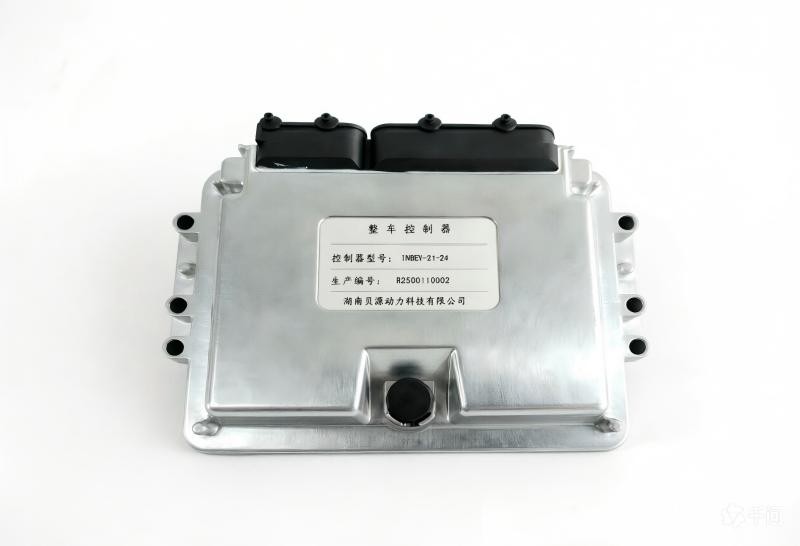

RCU controller function:
Control the engine speed, dynamically adjust the output power according to the load demand, to achieve stable output and energy saving effect.
Function of the whole vehicle controller:
The core control component of the electric vehicle, coordinating and controlling various sub-systems.
Collecting signals of accelerator pedal, brake pedal, gear and so on.c
Controls torque and speed from the point of view of the whole car, balancing power and comfort.
Controls the safe driving of the car.
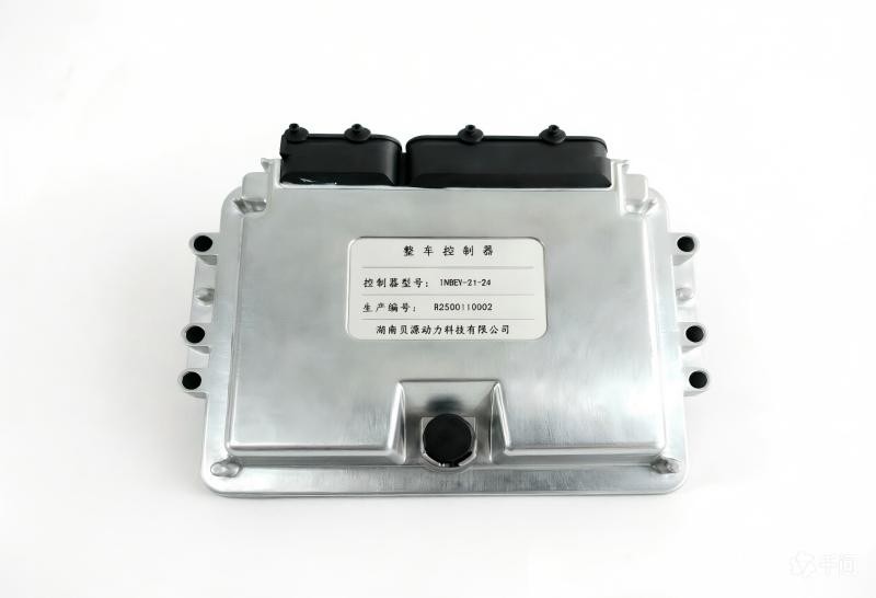
RCU controller function:
Control the engine speed, dynamically adjust the output power according to the load demand, to achieve stable output and energy saving effect.
Function of the whole vehicle controller:
The core control component of the electric vehicle, coordinating and controlling various sub-systems.
Collects signals from accelerator pedal, brake pedal, gear and so on.
Control the torque and speed from the perspective of the whole vehicle, taking into account the power and comfort.
Control the safe driving of the car.
Specific functions:
Vehicle drive control; brake energy feedback control
Vehicle energy optimisation; fault diagnosis and protection
Network management; vehicle status monitoring
| Function | Parameter | Description |
|---|---|---|
| Main control chip | TMS320F28335PGFA | Main frequency 150MHZ |
| Input voltage | 12V/24V compatible | Input voltage range: 9 to 32 VDC |
| Peak voltage | 36VDC | |
| Power consumption | Work properly<3W,Sleep<0.1W | |
| Simulate 5V output | 4‑channel | Maximum output current 500mA |
| General Analog Input | Route 11 | 5‑channel resistance detection, 6‑channel voltage detection |
| General Digital Input | Route 24 | 14‑channel high‑level active, 10‑channel low‑level active |
| Intelligent High‑Side Drive Interface | Route 10 | Features over‑voltage, over‑current, over‑temperature and short‑circuit protection |
| Smart Low‑Side Driver Interface | Route 10 | Comes with over‑voltage, over‑current, over‑heat and short‑circuit protection |
| CAN bus | Route 2 | One of the CAN channels supports remote wake‑up function. |
| Charging signal input | One channel each for CC signal and CP signal | Refer to national standards |
| PWM capture port | Route 2 | Supports 5‑24V square wave input |
| PWM output port | Route 2 | Output 5V frequency‑adjustable square wave |
| Wake‑up signal input | Route 1 | Signal edge trigger |
| Protection grade | IP67 |
